ATX Form Card
TL;DR
- You need one of these to use USB on your babyAT/ATX vintage motherboard (specially PCChips produced ca. 1997)
- It is rather impossible to buy one nowadays
- With some reverse engineering available on the internet I've designed, produced and successfully tested a PCB substitute
- EAGLE 6 project and Gerber files available in "Resources" section at the end of this post
The troublemaker
Some time ago I've stumbled upon a broken vintage motherboard. Well... technically it was in "I am unable to test it" condition, but upon closer inspection it had some traces broken, numerous spots of dirt and/or rain residue, general scratches and even dead insects stuck between RAM modules.
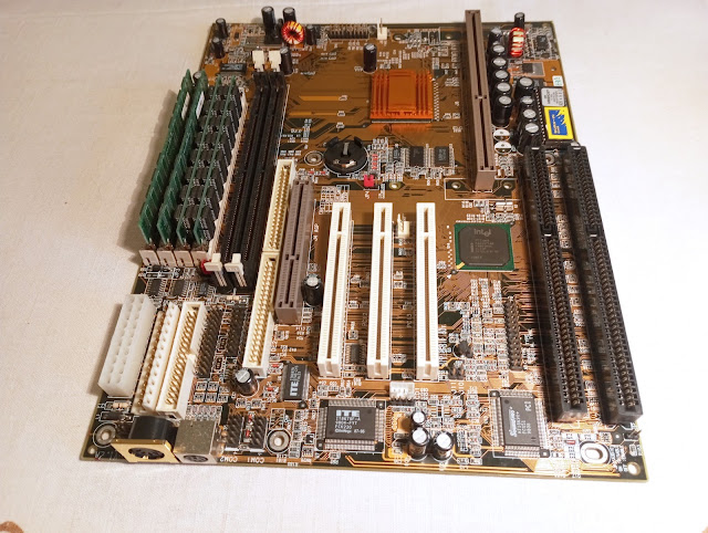
No "hopeless" damage, though, at least after visual inspection and it truly seemed worth saving as a great example of those motherboards that tried to squeeze in between baby AT and ATX standard. Ladies and gentlemen, let me present a PCChips M715 v1.2:
- baby AT form factor (incl AT keyboard connector)
- 2x ISA, 3x PCI, AGP
- support for Slot 1 CPUs
- both AT (P8+P9) and 20-pin ATX power connector
- support for both EDO (4 slots) and SD (2 slots) RAM
- integrated 2-channel IDE controller, USB controller and sound card (CMI8330)
The motherboard came bundled with Pentium II 233MHz SL2HD CPU. After numer of repairs (those are the subject for another post, maybe) it works like a charm. Or does it?
ATX Form Card
If you look closer at the connectors available, you can spot some non standard ones. Two 40-pin IDE connectors, 2x 10-pin RS232s, parallel port, FDD connector, even the PS/2 mouse connector header (third! as you'll see in a moment)... Yet we're missing something. There is no ATX rear panel (mainboard is AT after all!) and still there is no place to connect headphones, nor a thumb drive.
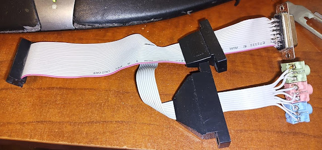
While solution to this riddle in case of audio connectors is rather simple, at least in the technical aspect (there is a pin header for a simple line in-mic in-line out-game port bracket), we are still unable to test the USB functionality.

(https://retrocomputing.stackexchange.com/questions/25069)
Reverse engineering
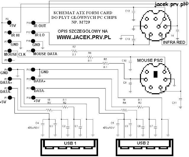
If we can't buy it, let's make one! Neither PCB nor circuitry looks complicated.The first problem is that some components are not labelled. Another one is that despite numerous potos available on the internet, I was unable to fully reverse engineer component connections. Photos below (which are the best I could find picturing PCB layout) were, sadly, not enough for instance to look under mini DIN ports :(
Let's focus on this circuit for a moment. While it gives you some idea on how "complicated" the whole device is, please note that numbers of compnents don't match those on PCB's silkscreen. Also the 0R1 resistors look rather like SMD ferrite beads to me. Finally, schematics completly skip F1 component. It is clearly mounted on a power rail of PS/2 and IR-DA ports. It could be a diode protecting mouse/IR transceiver attached to DIN port from reverse polarity, it could be some kind of fuse, as PCB marking indicates, but the closest thing i could match visually is another ferrite bead, THT-mounted this time.
Rest of the components is absolutely standard, including "Berg" style USB connectors, 8- and 6- pin mini DINs, 2x9 pin 2.54 header, some MLCCs, electrolytics and resistors.
The assembly
With schematics available, first design problem is to find a PC extension card bracket with holes layout suitable for two USBs and two mini DINs. Those are non-srandard ones and having my prevois experience in mind I'd prefer to avoid drilling holes in existnig bracket myself.
Fortunately a 2xUSB + 2xPS/2 setup can be found in some contemporary extension cards commonly avaliable on ebay, such as:
- tried to route traces as close as possible to original
- yellow soldermask was a wrong choice after all. Visually a transparent one would match motherboard (and the original card!) better, but PCBWay does not seem to offerit
- used 1206 (3216 metric) SMD components, while original was built with smaller ones; didn't want to bother with soldering
- tried to conserve pin numbers, although numbering scheme of original card makes no sense
- ribbon connector cable can be easily build on one's own; 2x9 2.54 connectors are widely available on AliExpress.
Talking about money, I've decided to produce 5 pieces which is probably the most reasonable minimum. Brackets (the whole USB+PS/2 PCI cards) costed me 12.4 EUR/13.7USD a piece (incl. shipping). A set of 5 PCBs is 13.2 USD total on pcbway.com, and please note they charged me extra for yellow soldermask! Two USB ports and one PS/2 ports per piece were scavenged off the PCI cards. Rest of the components was locally available at neglegible cost, let's say 5 USD total. As for connector cables, a set of 10 pcs of 2x9 connectors took mi 3 USD and I've already had a ribbon cable.
This adds up to 18 USD / piece, if I'm not mistaken.
Testing
Using the following "professional" test setup I was able to prove choice of components and trace routing decisions were right.
BIOS on my M715 is of graphical type! And it supports USB keyboard and PS/2 mouse out of the box! Although placing ferrite bead on one trace and 10R on another of differential USB data pair seems bizarre at first sight, I believe designers of the original card would know what they were doing.

I am not sure which USB speed my heyboard uses. It's probably Low Speed, so in order to test the card with maximum USB clock frequency, I had to use Windows 98 SE and USB 2.0 pendrive. Could you believe a thumb drive requires an external driver to run properly on Win98?! Good thing HID keyboard works out of the box. Luckily the tests were successful. I was able to read and write multiple files from/to the pendrive.
Up to this day I am unable to test IrDA port. First of all, there are claims that M715 does not support IrDA at all. On the other hand I'm pretty sure I saw IrDA in BIOS as a mode of operation of COM2. Would signals then have been routed to mini DIN on Form Card instead of COM2 if this option has been enabled?
It looks like typical IrDA transceivers use USB, while earlier ones convert RS-232 signals to infrared light. The only mention of IrDA transceiver with 8-pin connector I was able to find was HP C4103A IrDA module for LaserJet printers. It still is available second-hand, but for now I'm going to pass. After all, the USB is what I was missing the most on this motherboard. Maybe I'll test IrDA in the future.
Resources
- You can find EAGLE project, Gerber files and BOM on GitHub: https://github.com/jan-baranowski/atx-form-card
- Reverse engineering report by Jacek Głogowski can be found at https://jacek.unixstorm.org/elektronika/atx-form-card.html
- PCChips M715 v1.2 is well documented on TRW: https://theretroweb.com/motherboards/s/pcchips-m715-v1-2
- Some information about audio bracket can be found at StackExchange: https://retrocomputing.stackexchange.com/questions/25069
- There is a detailed article about HP C4103A and converting it to work with standard COM port: http://www.colin99.co.uk/extras/irda/hp_c4103a_irda.htm
- Moreover, details on C4103A itself and its' 8-pin mini DIN connector can be found (in german!) at https://www.infrarotport.de/mobo/asus_hp-c4103a.htm


Hello Janek, thanks for posting about this ATX form card. Do you have any of them to sell? I'd like to buy two of them for old AT motherboards I have, and can't find any. I am in California.
OdpowiedzUsuń